The common-emitter circuit
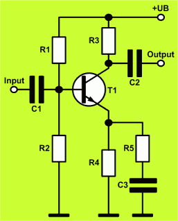
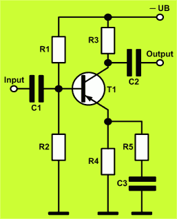
Schematic of the common-emitter circuit with NPN- and PNP-BJT
The pictures show the schematics of the common-emitter circuit with NPN transistor and with PNP transistor.
Fields of application for the common-emitter circuit
The common-emitter circuit is a basic transistor amplifier with voltage gain and current gain. It has a medium input impedance and a medium output impedance. This circuit offers the highest power gain of the three basic transistor amplifier circuits. The common-emitter circuit is suited for an AC-voltage amplifier in a wide area of application. It is often used as an amplifier stage in audio circuits or radio frequency circuits.
How to design a transistor amplifier in common-emitter configuration
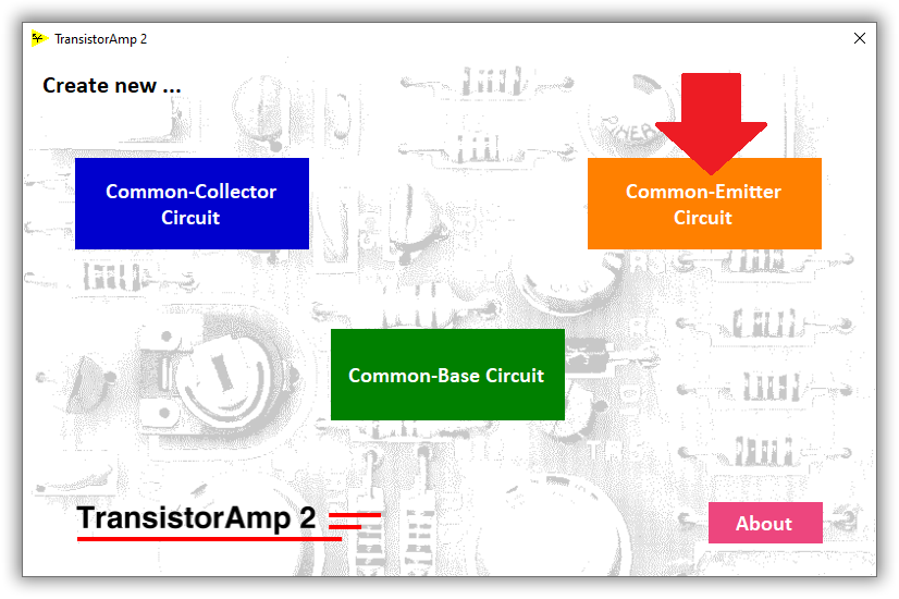
Transistor amplifiers in common-emitter configuration can be designed with TransistorAmp 2 software. Start TransistorAmp 2 and click the Common-Emitter Circuit button:
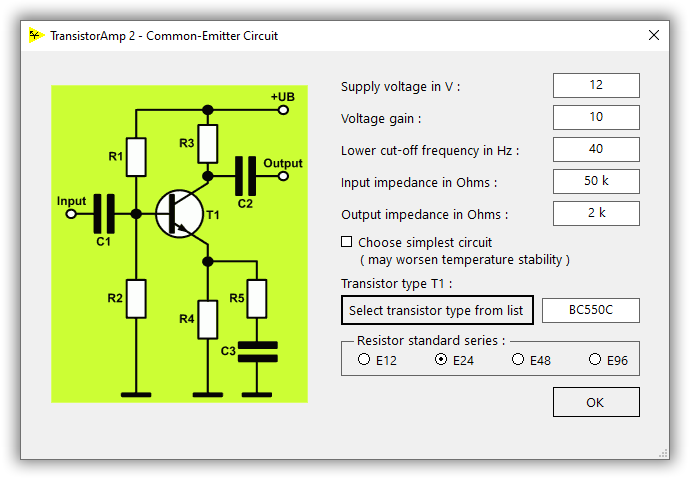
Now, the dialog Common-emitter circuit appears. Here you must input all parameters of your amplifier circuit:
To select the transistor type for your circuit, you must click the Select transistor type from list button and choose the transistor type within the next dialog:
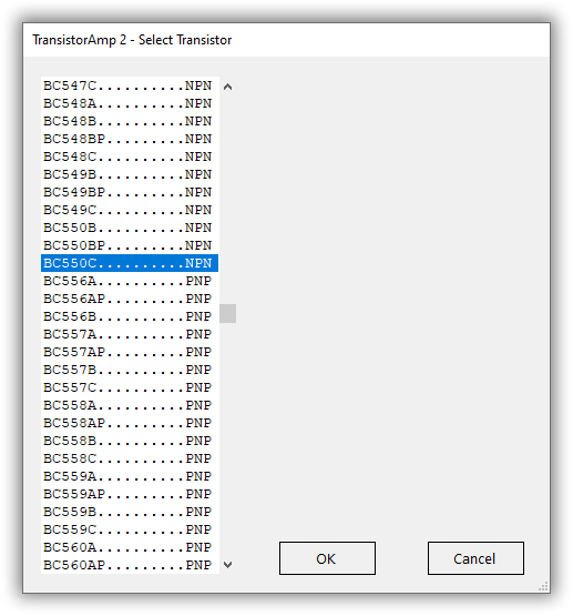
TransistorAmp 2 contains almost every usual type of bipolar transistor (thousands of types). So, you will certainly find there the transistor type you need. After having chosen a transistor type, you must click on OK and you will get back to the previous dialog (where you specify your amplifier). Now, it contains the transistor type which you have selected. You can click on OK. Then, the dialog closes and you will see immediately the design result of your new transistor amplifier:
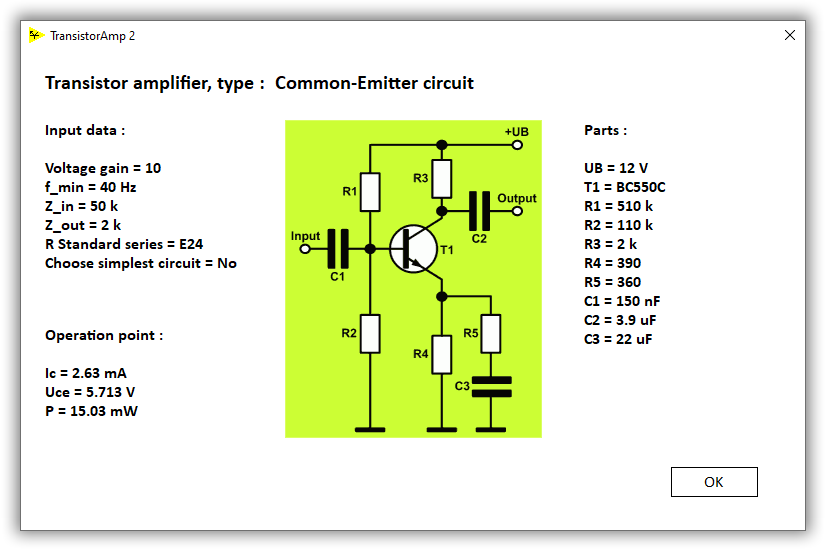
Here, you can see your input parameters, the circuit and the values of all components. Furthermore, you can see the most important parameters of the operation point, i.e. collector current, collector emitter voltage and power consumption.
If you want to change any parameter of the circuit, simply click again on New Amplifier - Common-Emitter circuit and you will see, that the input dialog remembers all of your inputs, so it is easy for you to make changes.
If you want to save your result, click the Save Result button, and input a file name and save the file.
Here, you can see the result file from our example: Amplifier in common-emitter configuration
If you want to simulate your circuit, click the Simulate button.
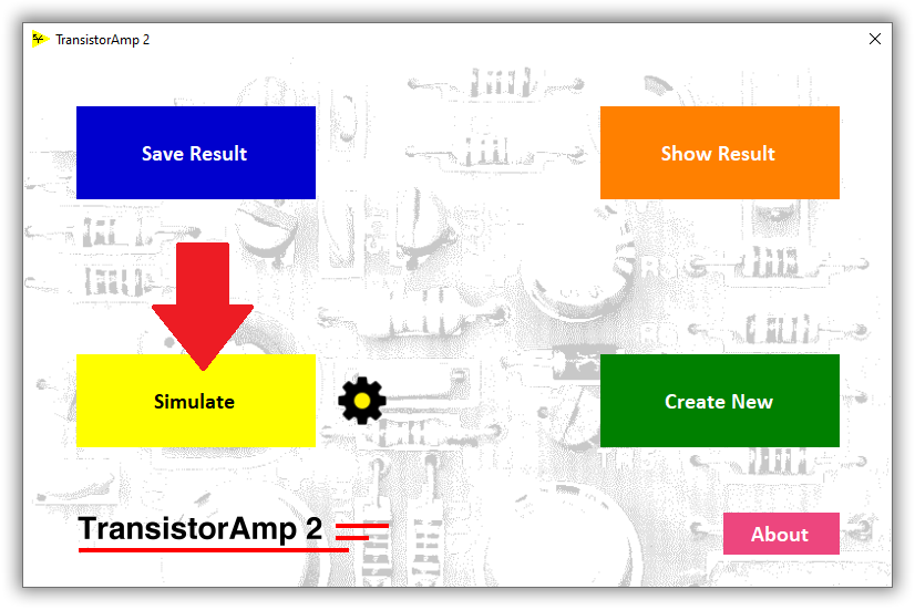
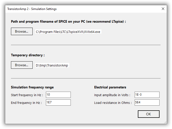
The first time you do this, you must input some settings:
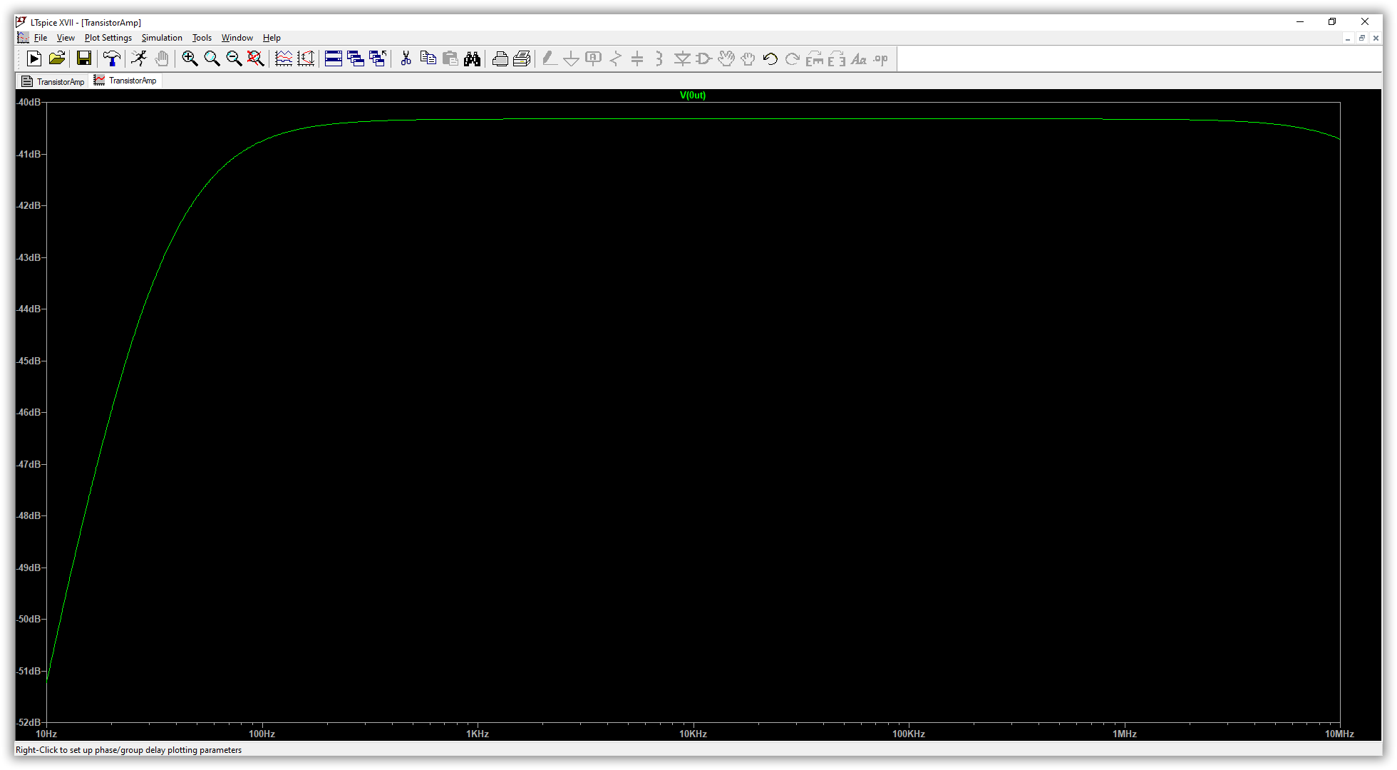
The simulation (AC sweep) in LTspice shows the output signal (input amplitude: 1 mV, i.e. -60 dB):
© Circuit Experts 2024
Imprint
· Privacy Policy
· Deutsch
